This is an old revision of the document!
Table of Contents
Apple IIc Plus: SmartPort Secrets
Written on 2018/06/12.
I've been actively working on disassembling the Apple IIc Plus firmware in order to find out how its 3.5" firmware works with the unique hardware of the machine to support the “dumb” 3.5" floppy drives.
A lot of it involves knowing how the 3.5" floppies are formatted at the low-level. The Woz state machine is the basis for operations with both the 3.5" and 5.25" floppies, so there are bound to be similarities between the the low level formats, and there are. In particular, the following are common to both:
- Address and data prologues
- Self-sync bytes
- 6&2 disk bytes (“nibbles”)
The 3.5" Floppy Format
The 3.5" floppy sectors are formatted as follows:
| Address Field | Data Field |
The address field of the 3.5" floppy is as follows
| 5+ self-syncs | $D5 $AA $96 | TT SS DD FF KK | $DE $AA “off” |
Where TT is the low 6 bits of the track, SS is the sector number, DD is the side and upper bit of the track number, and FF is the format specifier (sides+sector interleave), and KK is the checksum.
The data field is:
| 5 self-syncs | $D5 $AA $AD | 699 disk bytes | KK KK KK KK | $DE $AA “off” |
In this case, we can see the address and data prologues are the same between the 5.25" and 3.5" formats. The epilogues are defined differently. In we are used to $DE $AA $EB, but instead of $EB we have “off”… this is defined in the official documentation as a “pad byte where the drive electronics were turned off.” Code that reads a 3.5" disk should not assume the byte contains anything useful. In fact, ProDOS ignores this byte even when reading a 5.25" floppy.
Unlike the 5.25" floppy address header, the 3.5" floppy address header is coded in 6&2 format and can be decoded from the standard nibble table.. E.g. if SS contains $96, the address is for sector 0, if it contains $97, the address is for sector 1.
The 5.25 Floppy Format
The disk format we are all used to with the 5.25" floppies is well-explained in Beneath Apple DOS. To summarize what a sector header looks like for one:
| self-syncs | $D5 $AA $96 | VV VV TT TT SS SS KK KK | $DE $AA $EB |
In the case of the 5.25" floppy, the volume, track, and sector are encoded in the 4&4 format - each byte is split into the odd and even bits, interleaved with ones and written to the disk. Decoding involves reading the first byte, shifting it, and ANDing it with the second byte.
What's in an Aux Firmware Bank, Anyway?
Since there is a high degree of code commonality in the main firmware bank of the IIc Plus vs the ROM $4 //c, I've been mostly concentrating on the aux firmware bank, where I found the following code:
; Look for $D5 $AA $96 - Sector address mark
LDD06:  lda     LC0EC                           ; read IWM
        bpl     LDD06                           ; wait for byte
LDD0B:  cmp     #$D5                            ; is it $D5?
        bne     LDD00                           ; nope, go try again (code not shown)
LDD0F:  lda     LC0EC                           ;
        bpl     LDD0F                           ;
        cmp     #$AA                            ;
        bne     LDD0B                           ;
        ldy     #$03                            ; we are going to get 4 things below
LDD1A:  lda     LC0EC                           ;
        bpl     LDD1A                           ;
        cmp     #$96                            ;
        bne     LDD0B                           ; look for address mark some more
; have address mark, now read the address field.
        sei                                     ; just in case, I guess... it was disabled earlier
        lda     #$00                            ; init checksum
LDD26:  sta     $3B                             ; update checksum
LDD28:  lda     LC0EC                           ; read byte
        bpl     LDD28                           ; wait for it...
        rol     a                               ; ?
        sta     $3E                             ; and save it
LDD30:  lda     LC0EC                           ; next byte
        bpl     LDD30                           ; wait for it...
        and     $3E                             ; ????! wait a second, this looks like 5.25 address data
        sta     LCE04,y                         ; save in MIG RAM
        eor     $3B                             ; update checksum
        dey                                     ; next 2 bytes, it seems...
        bpl     LDD26                           ; if not done, read next pair
        tay                                     ; should be 0 if we processed checksum
        bne     LDCE7                           ; if not, I/O error
Note my comments reflecting my surprise at finding this buried in the Apple IIc Plus firmware. This is code that clearly reads the 4 values from the address field of a 5.25" floppy. But why is it here? I left that question in my head as I continued disassembly.
Things that Lurk in the ROM
Later on, I found this in the shared SmartPort/ProDOS block device code:
LE3DF:  stz     LCE0E                           ; clear this in MIG page 0
        tay                                     ; move unit number to Y
        cmp     #$05                            ;
        bcs     LE3FB                           ; if 5 or bigger...
        lda     $07F8                           ; slot $Cn was put here
        cmp     #$C6                            ; is slot 6?
        beq     LE404                           ; treat this one differently
Okay, that's very interesting. The SmartPort code clearly expects and special cases a reference to slot 6, which as we know is used for 5.25 floppies in the IIc Plus (and //c).
Well, time to go poking around.
Just How Does the IIc Plus Boot Slot 6?
On a hunch, I decided to go looking at the boot code for the machine. It starts like this:
LC600:  ldx     #$20                            ; Disk II boot code generally starts this way
        ldy     #$00                            ; Also contains the ID bytes
        stz     $03                             ; The code from here matches the //c
        stz     L003C                           ; which has a limited retry count for boot sector
        lda     #$60                            ; we are at a fixed location, we know this is slot 6
        tax                                     ;
        stx     $2B                             ; save it the various places boot code expects
        sta     $4F                             ;
        phy                                     ;
        lda     LC08E,x                         ; IWM Q7 OFF
        lda     LC08C,x                         ; IWM Q6 OFF - going to read data register
        ply                                     ;
        lda     LC0EA,y                         ; IWM - select drive 1
        jsr     LC763                           ; IIc Plus has this.... //c does not
So what's at $C763?
LC763:  ldx     #$05                            ; 6 things
LC765:  lda     LC56C,x                         ; Copy from $C56C
        sta     $42,x                           ; To $42
        dex                                     ;
        bpl     LC765                           ;
        jsr     LC64E                           ; Call this thing
        eor     #$28                            ; see if A=$28
        bne     LC775                           ; if not, more stuff to do
        rts                                     ; otherwise, exit
LC775:  bit     LC0E9                           ; IWM - turn on drive motor
        lda     #$01                            ;
        sta     $42                             ;
        jmp     LC58E                           ; go do more stuff
Hmmm… normally when you write 6 bytes to $42, you are setting up a “ProDOS Intelligent Disk Controller” call as specified in the ProDOS 8 Technical Reference Manual.
So what's at $C56C? $FF $60 $00 $08 $00 $00
Well, that's kind of odd but if it were a block driver call, the command would be $FF (undefined), unit for slot 6, drive 1, buffer $0800, block 0. I guess we'll have to see what the code at $C64E does:
LC64E:  sec                                     ;
        bcs     LC652                           ;
        clc                                     ;
LC652:  jmp     LC567                           ; more stuff to do
LC567:  lda     #$C6                            ; a slot 6 reference
        jmp     LC510                           ; Now *this* is interesting
So I know that $C510 is part of the slot 5 SmartPort/Block Device code… so I will give the context before $C510:
LC50A:  sec                                     ; this is the "Intelligent Disk Device" entry point
        bcs     LC50E                           ;
LC50D:  clc                                     ; this is the SmartPort entry point
LC50E:  lda     #$C5                            ; a slot 5 reference
LC510:  sta     $07F8                           ; save in screen hole
        lda     #$81                            ; save the language card state
        bit     LC012                           ; to be restore later with accesses to $C000,X
        bpl     LC523                           ;
        lda     #$8B                            ;
        bit     LC011                           ;
        bpl     LC523                           ;
        lda     #$83                            ;
LC523:  tax                                     ;
        bit     LC089                           ; make sure ROM is present
        lda     #$00                            ;
        ror     a                               ; put carry into A (reflecting what entry point was used)
        cld                                     ; no decimals here!
        jsr     LC584                           ; this switches firmware banks and calls implementation
        bit     LC000,x                         ; restore LC state
        bit     LC000,x                         ;
        lda     $0478                           ; contains error code, if any
        ldx     $04F8                           ; load X from a screen hole
        cmp     #$01                            ; set carry if error
        ora     #$00                            ; Make sure Z flag is set?
        rts                                     ;
So the code at $C64E calls the slot 5 block device or SmartPort entry points, but sets up the call to look like it's coming from slot 6! This is kind of a big deal.
Now this makes some sense:
LC763:  ldx     #$05                            ; 6 parameter bytes
LC765:  lda     LC56C,x                         ; copy from $C56C
        sta     $42,x                           ; to $42
        dex                                     ;
        bpl     LC765                           ;
        jsr     LC64E                           ; call slot 6 ProDOS block device driver
        eor     #$28                            ; see if A=$28, the error code for no device connected
        bne     LC775                           ; if no error, don't exit yet
        rts                                     ;
LC775:  bit     LC0E9                           ; IWM - turn on drive motor of the unit we just accessed
        lda     #$01                            ; lie and say we did a block device driver read command
        sta     $42                             ; update command in parameter table
        jmp     LC58E                           ; see below
OK, so now we could look at $C58E, but I already know what's there, it's code that's been in every Apple //c: a routine to generate a denibbilizing routine that 5.25 boot sectors expect to be present.
When that returns, we go back to the code in slot 6 that brought us here, that mostly looks like the original //c boot code.
Look Ma, No DOS!
OK, we found what looks like a nice little ProDOS block device and SmartPort driver in the IIc Plus ROM, but does it work?
Well, it turns out that's really easy to test. The IIc Plus has a built-in mini-assembler that is up to the task. So let's test the block device interface. So I'll reboot the machine without a disk in the drive, so we know that the we are just using the firmware. For testing, I then inserted a formatted ProDOS disk.
]CALL -151
*!
!300:LDX #5
! LDA 320,X
! STA 42,X
! DEX
! BNE 302
! JSR C64E
! STA 330
! STX 331
! STY 332
! RTS
!
*320:00 60 00 10 02 00
What we have here is a small routine to set up a block device call and do it through the entry point we found. At $320, I've asked for the STATUS call ($00) for slot 6, drive 1 ($60 in terms of ProDOS unit numbers). I've also set up the buffer address to $1000 and block number to $0002. We don't need them for the STATUS call, but they will be handy later. Finally, after the call completes, we put the values of A, X, and Y somewhere we can read them. The A register always contains an error code, $00 if no error. For STATUS, X and Y contain the low and high bytes of the number of blocks on the device.
Ready for action:
*300G
*330.332
0330- 00 18 01
*
Success! $0118 blocks were indicated for the device. That's 280 in decimal, and exactly how many blocks are on a standard Apple II 5.25" floppy disk.
So does it read a disk?
*320:01
*300G
*330
300- 00
*1000.100F
1000- 00 00 03 00 FC 50 52 4F
1008- 44 4F 53 2E 32 2E 34 2E
*
That's exactly what we expect to see at block two of this disk, which is the first volume directory block. The contents are two bytes for the link to the previous block (none), two bytes for the link to the next block (block 3), a byte for the storage type ($F) and name length ($C) of the volume, followed by the volume name, which in this case is PRODOS.2.4.2.
There are two more commands we can test, WRITE ($02) and FORMAT ($03):
*320:02
*300G
*330
300- 00
*320:03
*300G
Well… I now have a freshly-blanked disk. The formatting code appears to use the “hyper” method, it took very little time at all.
So, about that device command $FF? I initially suspected that it's “go boot that thing if possible” since it appears in the boot ROM, however this is not borne out by testing:
*320:FF
*300G
*330
300- 00
*1000.100F
1000- 00 00 00 00 00 00 00 00
1008- 00 00 00 00 00 00 00 00
It appears that it just reads the block, and nothing else. So the boot code reads block 0, and then goes to the old boot code to read track 0, sector 0. The net effect is that all of block 0 is in RAM at $0800, though.
ProDOS Driver Tricks
Now the question is, what happens when we replace the Disk II driver in ProDOS with the firmware driver? It's actually pretty easy to find out.
ProDOS keeps a device driver address table at $BF10-$BF1F in the Global Page. The first 16 bytes are for each slot's drive 1, and the second are for each slot's drive 2. Normally, the address for a Disk II is $D000, which is the address for the RAM-based driver within ProDOS itself.
So, to change the driver to the firmware driver we simply do (after booting ProDOS):
*BF1C:4E C6
*BF2C:4E C6
*CAT,S6

/PRODOS.2.4.2

 NAME           TYPE  BLOCKS  MODIFIED

 VIEW.README     BAS       1  15-SEP-16
*BITSY.BOOT      SYS       1  15-SEP-16
*QUIT.SYSTEM     SYS       1  15-SEP-16
*BASIC.SYSTEM    SYS      21  30-AUG-16
*COPYIIPLUS.8.4  SYS      56  28-FEB-89
*CAT.DOCTOR      SYS      28  22-FEB-90
...
Success!
What About SmartPort?
SmartPort has a lot of capabilities, and rather than write code to display everything it can tell us, I modified the Davex deschw command to do it instead. Here's a screenshot of it running on one of my machines:
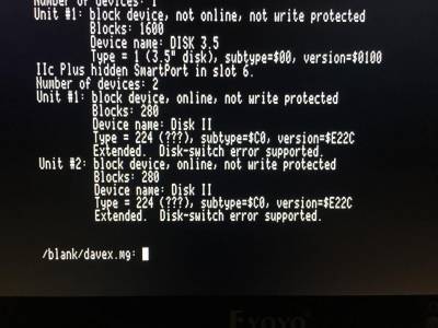
It looks like it doesn't give good values for some of the device details, but it shows that it basically works.
Cool.
Conclusion
That a secret device driver has been lurking in the Apple IIc Plus for decades without anything being written on it is… amazing. I'd like to think I was the first person outside of Apple to know about it, but who knows?
In any case, it's one hell of an Easter egg.
It also goes to show the twists and turns that reverse engineering old computers can take. I was originally attempting to understand the 3.5" floppy code in the Apple IIc Plus, and along that journey, I got to take a subquest and discover something completely unexpected.
—
I'd like to thank Léon Bottou, whose additional work on understanding the MIG chip and subsequent development of a working Apple IIc Plus emulation gave me motivation to continue disassembling the Apple IIc Plus code and provided an easy testbed to work with before trying it out on real hardware.